EP2C5T144 FPGA tester
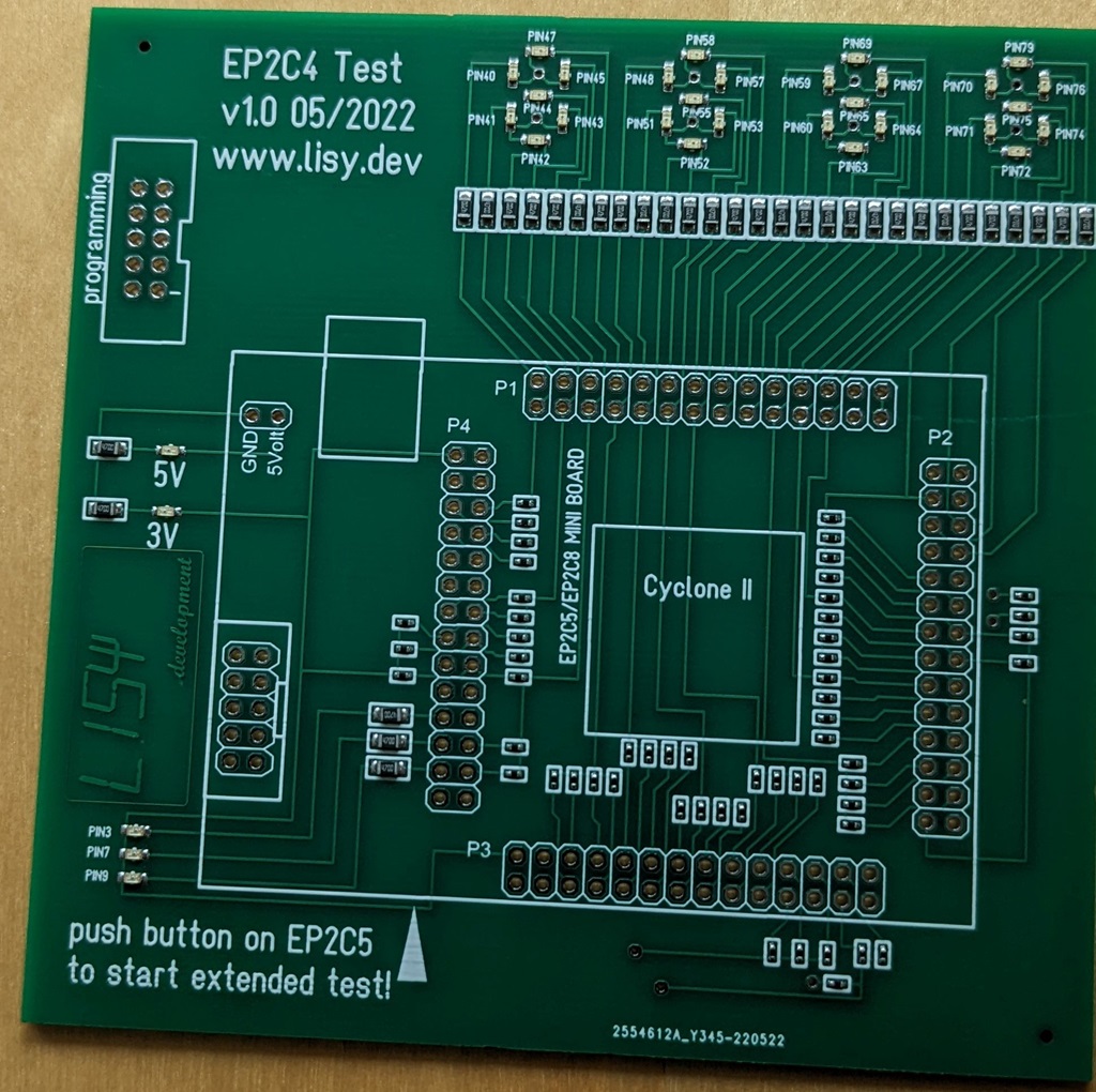
Test PCB for cheap EP2C5T144 FPGA boards which are often buggy. In most cases this is because of bad (SMD) soldering. With my tester you can identify which IOs are failing and can try to solve the issue by 'resoldering' the Pins of the FPGA chip.
Note: update to latest SW (v09) recommended, as old version v03 had false positives!
FPGA 'GOOD'
failed IOs '21' '93' and '101'
documentation
New in software version 0.9
At start the LEDs ( which building a 'sort of' 7segment display) show 'LISY' for a few seconds. Then each of LEDs is lit seperately to detect 'shorts' between the LEDs. After that '8888' is show, which set all LEDs to ON.
This is the first check of 28 IOs. These IOs are needed for the 'extended' test routine. Watch carefully that all LEDs are working. The coresponding Pin is written on the PCB (see also picture below)
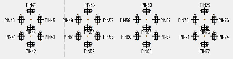 Pin numbering of the 28 LEds
Once confirmed that all LEDs are ON you can start the extended test by pushing the switch on the backside of the EP2C5T144 board. ( Note: if one of the LEDs is not ON you need to solve this issue before continuing to the extended test!)
The extended test will check the other 49 IOs on the FPGA by setting them to high & low and reading the value afterwards.
If the board is OK after a few seconds you can see 'GOOD' on the four 7-segment on the top (video 1)
If an error is detected (video 2) the 7-segment will show the number of the failing pin. You need to push the switch again to continue testing. At the end of the test you will see 'Err' on the 7-segment.
The failing pin is leading 'L' when the test is reading low-level when expecting high level and a leading 'H' when expecting high level but reads low level. In 'video2' the 'L' errors are simulated by not soldering some of the header pins.
 tester preassembled by JLCPCB
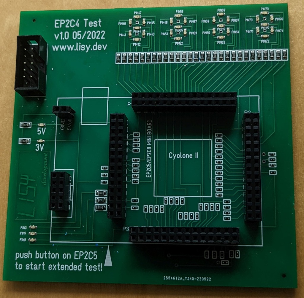 Check if your FPGA is working by using my FPGA checker!
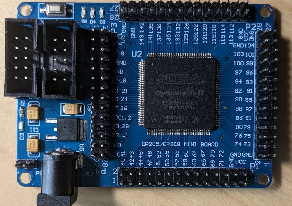 EP2C5T144 pin numbering